ELECTRONIC SYMBOLS (INFO)
Power supply symbols
Cell
Supplies electrical energy. The larger line is positive (+). A single cell is often called a battery, but strictly speaking a battery is two or more cells joined together.
Battery
Supplies electrical energy. A battery is more than one cell. The larger line is positive (+).
Solar Cell
Converts light to electrical energy.
The larger line is positive (+).
DC supply
Supplies electrical energy.
DC = Direct Current, always flowing in one direction.
AC supply
Supplies electrical energy.
AC = Alternating Current, continually changing direction.
Fuse
A safety device which will 'blow' (melt) if the current flowing through it exceeds a specified value.
Transformer
Two coils of wire linked by an iron core. Transformers are used to step up (increase) and step down (decrease) AC voltages. Energy is transferred between the coils by the magnetic field in the core, there is no electrical connection between the coils.
Earth (Ground)
A connection to earth. For some electronic circuits this symbol is used for the 0V (zero volts) of the power supply, but for mains electricity and some radio circuits it really means the earth. It is also known as ground.
Output device symbols

Lamp (lighting)
A transducer which converts electrical energy to light. This symbol is used for a lamp providing illumination, for example a car headlamp or torch bulb.

Lamp (indicator)
A transducer which converts electrical energy to light. This symbol is used for a lamp which is an indicator, for example a warning light on a car dashboard.
Heater
A transducer which converts electrical energy to heat.

Motor
A transducer which converts electrical energy to kinetic energy (motion).

Bell
A transducer which converts electrical energy to sound.

Buzzer
A transducer which converts electrical energy to sound.
Inductor, Coil, Solenoid
A coil of wire which creates a magnetic field when current passes through it. There may be an iron core inside the coil. It can be used as a transducer converting electrical energy to mechanical energy by pulling on something magnetically.
Switch symbols
Push-to-make switch
A push switch allows current to flow only when the button is pressed. This is the switch used to operate a doorbell.
Push-to-break switch
This type of push switch is normally closed = on, it is open = off only when the button is pressed.
SPST, on-off switch
SPST = Single Pole, Single Throw. Current flows only when the switch is in the closed =on position.
SPDT, 2-way switch
SPDT = Single Pole, Double Throw. A 2-way changeover switch directs the flow of current to one of two routes according to its position. Some SPDT switches have a central off position and are described as 'on-off-on'.

DPST switch
DPST = Double Pole, Single Throw. A dual on-off switch which is often used to switch mains electricity because it can isolate both the live and neutral connections.
DPDT switch
DPDT = Double Pole, Double Throw.
This switch can be wired up as a reversing switch for a motor. Some DPDT switches have a central off position.
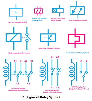
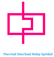
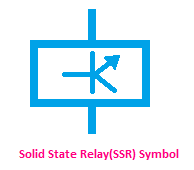
Relay
An electrically operated switch, for example a 9V battery circuit connected to the coil can switch an AC mains circuit. The rectangle represents the coil.
NO = Normally Open, COM = Common, NC = Normally Closed.
Resistor symbols
Resistor
A resistor restricts the flow of charge. Uses include limiting the current passing through an LED, and slowly charging a capacitor in a timing circuit.
Some publications use the old resistor symbol: ![]()

Rheostat variable resistor
A rheostat has 2 contacts and is usually used to control current. Uses include controlling lamp brightness or motor speed and changing the rate of flow of charge into a capacitor in a timing circuit.
Potentiometer variable resistor
A potentiometer has 3 contacts and is usually used to control voltage. It can be used like this as a transducer converting position (angle of the control spindle) to an electrical signal.

Preset variable resistor
A preset is operated with a small screwdriver or similar tool. It is designed to be set when the circuit is made and then left without further adjustment. Presets are cheaper than standard variable resistors so they are sometimes used in projects to reduce the cost.
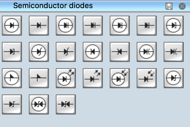
Diode symbols
Diode
A device which allows current to flow in only one direction.
Light Emitting Diode
A transducer which converts electrical energy to light. Usually abbreviated to LED.
Zener diode
A zener diode can be used to maintain a fixed voltage.

Photodiode
A light-sensitive diode.
Capacitor symbols
Capacitor, unpolarised

A capacitor stores electric charge. It can be used with a resistor in a timing circuit, for smoothing a supply (it provides a reservoir of charge) and can be used as a filter (blocking DC signals but passing AC signals). Unpolarised capacitors usually have small values, less than 1µF.

Capacitor, polarised
A capacitor stores electric charge. Polarised capacitors must be connected the correct way round. They usually have larger values, 1µF and greater. See above for uses.

Variable capacitor
A variable capacitor is used in a radio tuner.

Trimmer variable capacitor
This type of variable capacitor is designed to be set when a circuit is made and then left without further adjustment.
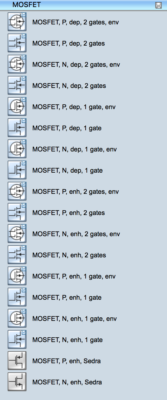
Transistor symbols

Transistor NPN
A transistor amplifies current and can be used with other components to make an amplifier or switching circuit. This symbol is for a bipolar junction transistor (BJT), the type you are most likely to use at first.

Transistor PNP
A transistor amplifies current and can be used with other components to make an amplifier or switching circuit. This symbol is for a bipolar junction transistor (BJT), the type you are most likely to use at first.

Phototransistor
A light-sensitive transistor.
Audio and Radio symbols

Microphone
A transducer which converts sound to electrical energy.

Earphone
A transducer which converts electrical energy to sound.

Loudspeaker
A transducer which converts electrical energy to sound.

Piezo Transducer
A transducer which converts electrical energy to sound.

Amplifier (general symbol)
An amplifier circuit with one input. Really this is a block diagram symbol because it represents a circuit rather than just one component.
Aerial (Antenna)
A device to receive or transmit radio signals. It is also known as an antenna.
Meters and Oscilloscope

Voltmeter
Measures voltage. The proper name for voltage is 'potential difference' but voltage is more widely used.

Ammeter
Measures current.

Galvanometer
A very sensitive meter used to measure tiny currents, usually 1mA or less.

Ohmmeter
Measures resistance. Most multimeters have an ohmmeter setting.

Oscilloscope
An oscilloscope is used to display the 'shape' of electrical signals - showing how they vary with time. It can be used to measure voltage and time periods.
Sensors (input devices)

LDR
A transducer which converts brightness (light) to resistance (an electrical property). LDR = Light Dependent Resistor
Thermistor
A transducer which converts temperature (heat) to resistance (an electrical property).
Wire and connection symbols
Wire
Connects components and passes current easily from one part of a circuit to another.
Wires joined
A 'blob' should be drawn where wires are connected (joined), but it is sometimes omitted. Wires connected at 'crossroads' should be staggered slightly to form two T-junctions, as shown on the right.
Wires not joined
In complex diagrams it is often necessary to draw wires crossing even though they are not connected. The simple crossing on the left is correct but may be misread as a join where the 'blob' has been forgotten. The bridge symbol on the right leaves no doubt!


]
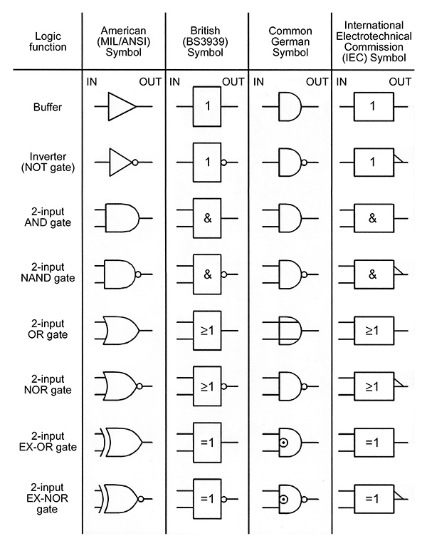
Fuses IEC Symbols


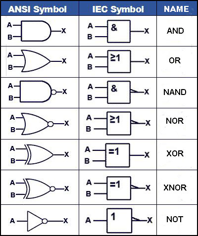

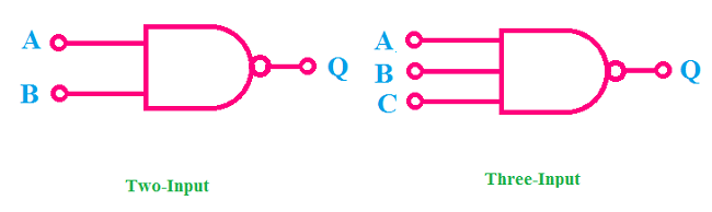
NAND Gate
NAND gate is a logical Gate which creates Low Output Signal only when all Inputs are High otherwise it creates High output signal. A NAND Gate is nothing but a combination of AND Gate and NOT Gate. Today we are going to discuss Truth Table, Internal Circuit Design, Symbol of NAND Gate.
![Exclusive OR [XOR] Gate Truth Table, Internal Circuit Design, symbol - ETechnoG](https://4.bp.blogspot.com/-ip-XTYipgjQ/XF_B2O8_A-I/AAAAAAAABQU/mjvwVlUuhtUOtDSTq124U21h-f59pbvWgCLcBGAs/s1600/XOR%2Bgate%2Bsymbol.png)
Truth Table of Exclusive OR (XOR) Gate:
Truth Table of Two-Input Exclusive OR (XOR) Gate:
|
A
|
B
|
Q
|
|
0
|
0
|
0
|
|
0
|
1
|
1
|
|
1
|
0
|
1
|
|
1
|
1
|
0
|